

The cavity resonators can be used as filters, duplexers, diplexers with known topologies such as combline, interdigital, dielectric resonance, waveguide structures, tubular, coaxial resonator cavity and more. Other types of cavity structures can be used to implement coaxial cables, wave guides, splitters, combiners, circulators, isolators, couplers, hybrids couplers, delay line, magnetrons, and suchlike.











RF and microwave resonant cavities typically include external connectors configured to couple the resonant cavities to other system, connectors between components typically cause RF performances degradation
The conventional manufacturing techniques involve a waste of natural metal recourses during the process, is not environmental effective/friendly.
The conventional manufacturing techniques is only suitable to limited types and designs of cavity resonators.
The cavity structures are constructed from a plurality of PCB’s The PCB made from dielectric and/or diamagnetic materials
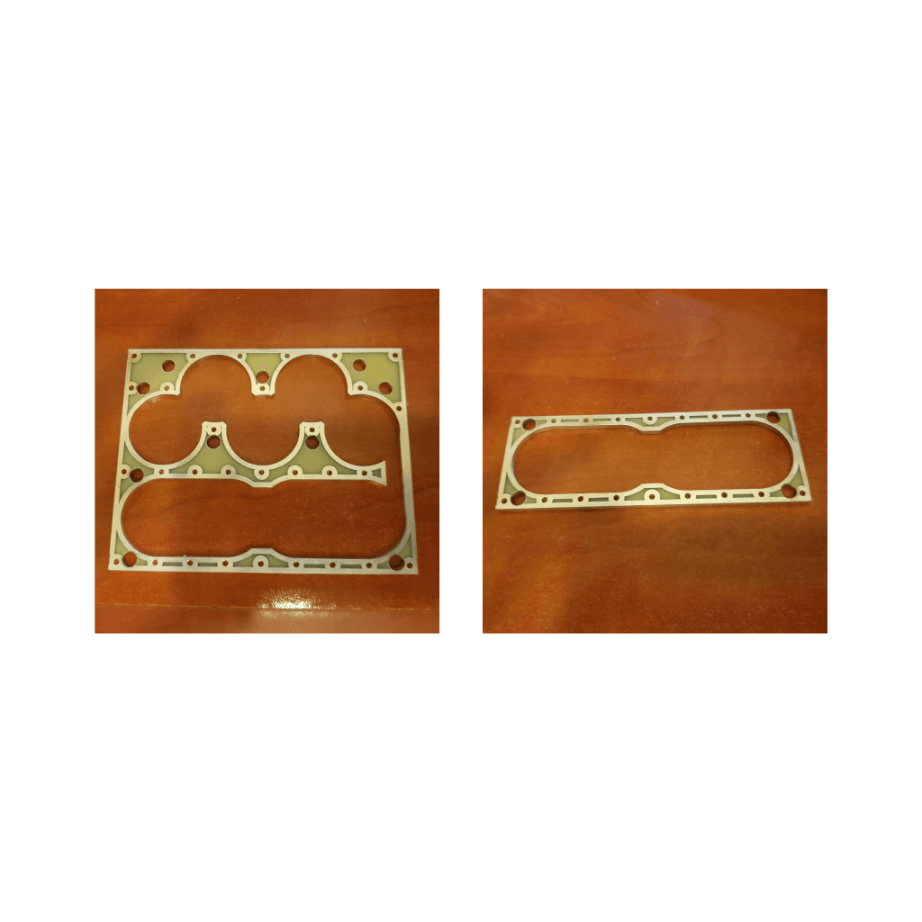
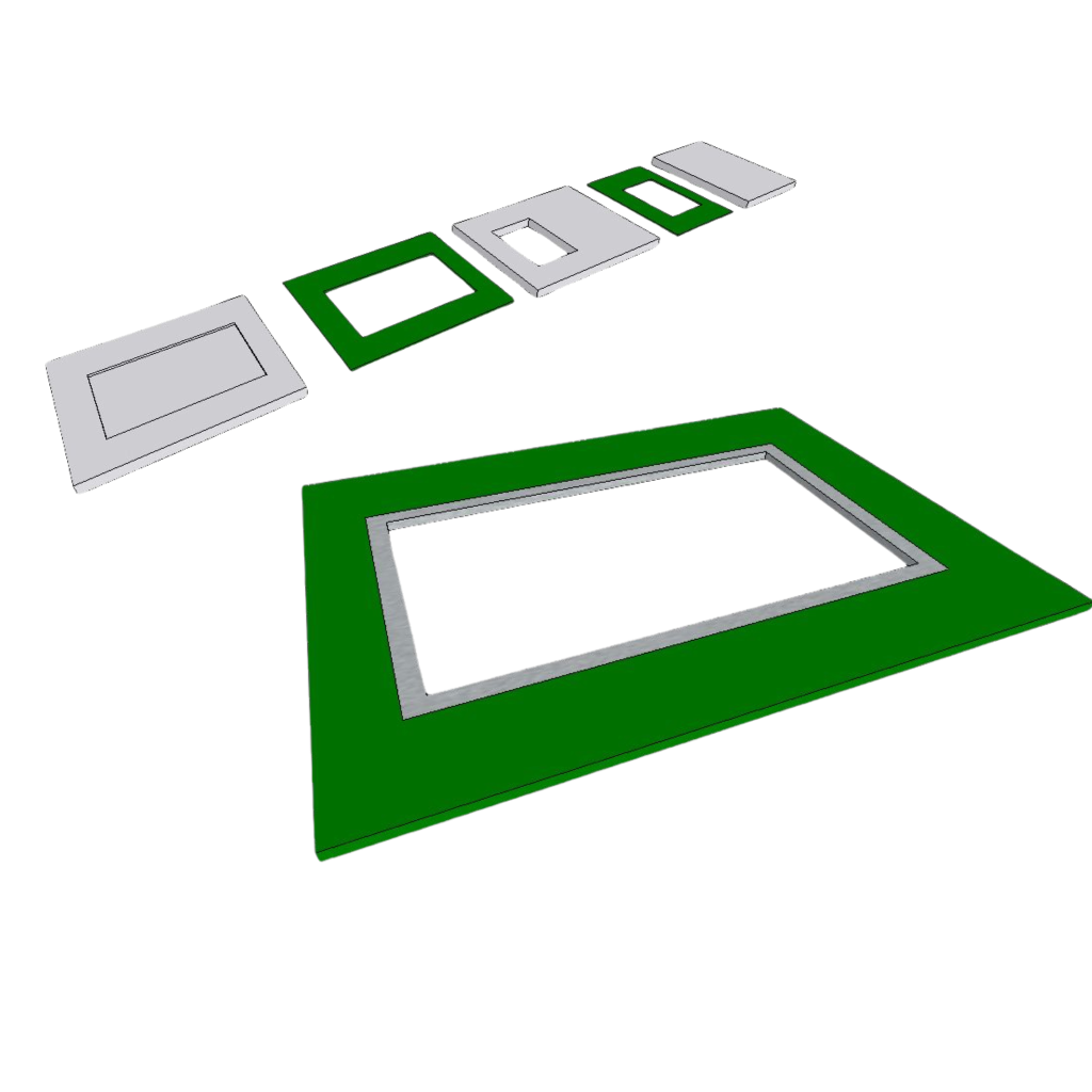
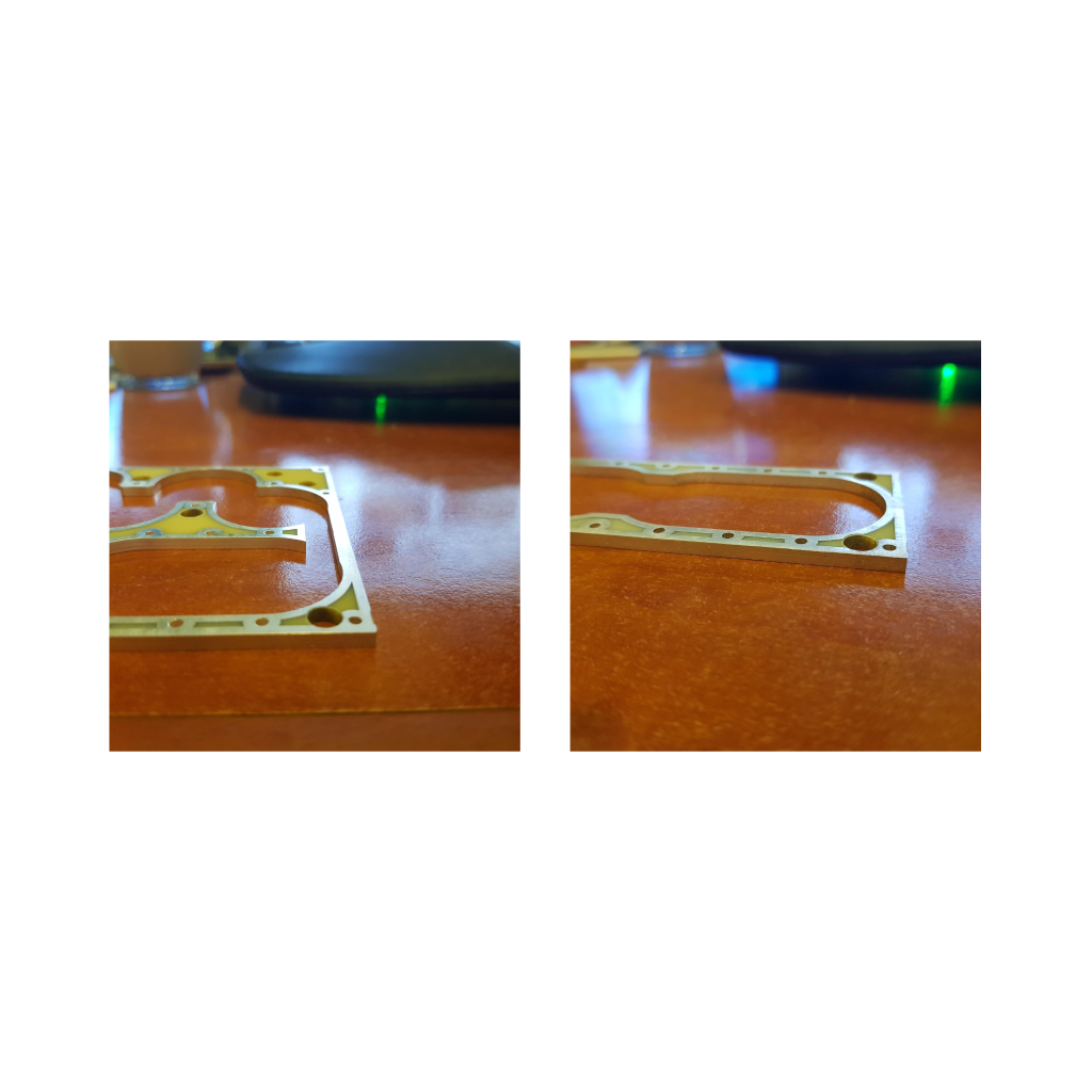
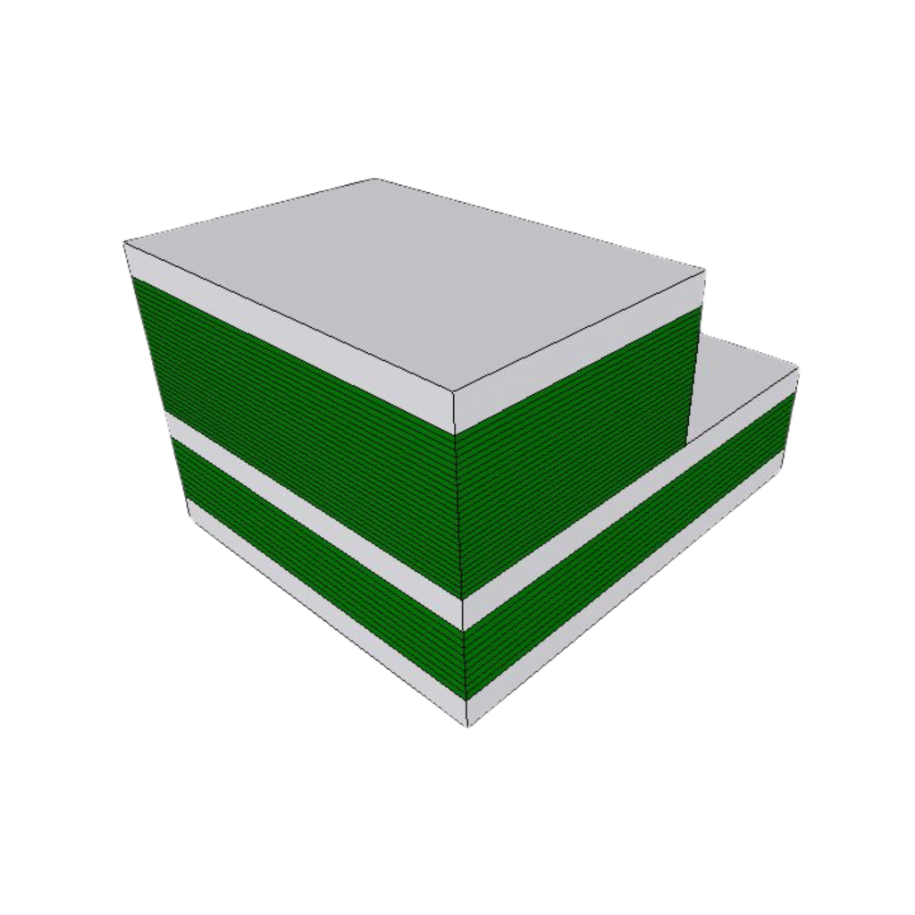
Plurality of flat boards walls that are stacked one on top of the other form a multilayered structure having channels constructed by the openings formed, such that continuous electrical conductivity is obtained along each channel by the conducting material layers applied on the openings.
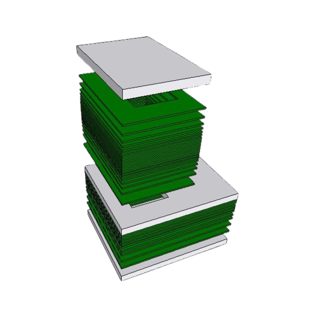
The topmost and bottommost boards are flat boards made of PCB or electrically conducting material which haven’t opening, configured to cover openings of the channels formed in the structure by their surface area to thereby form in the multilayered structure internal hollow cavities which surfaces are covered by electrically conducting layers.
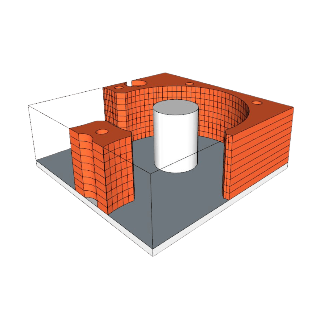
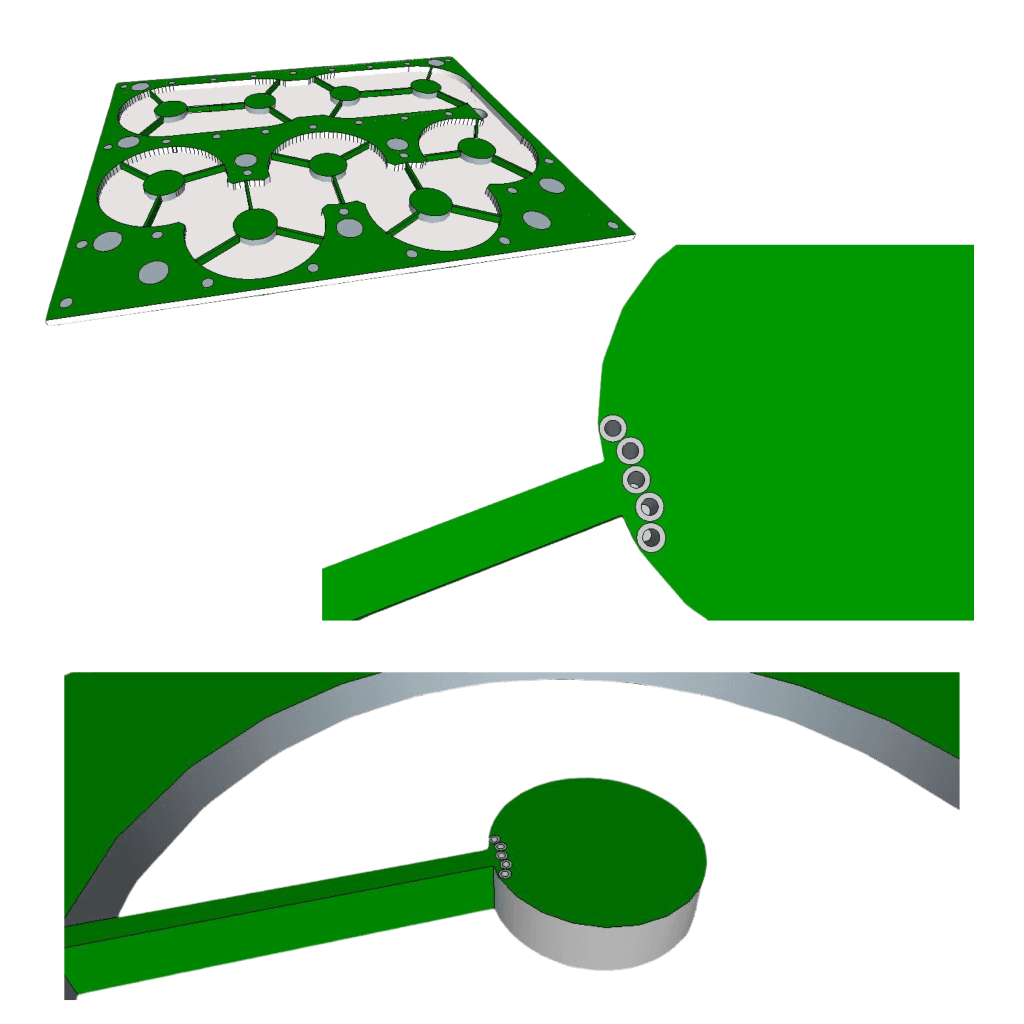
PCB Design Enables Creating And Holding The Rod Segment. The Conductance Of The Rod Persist By Design Metalized Vias Along Its Contour On The Connected Arms Location

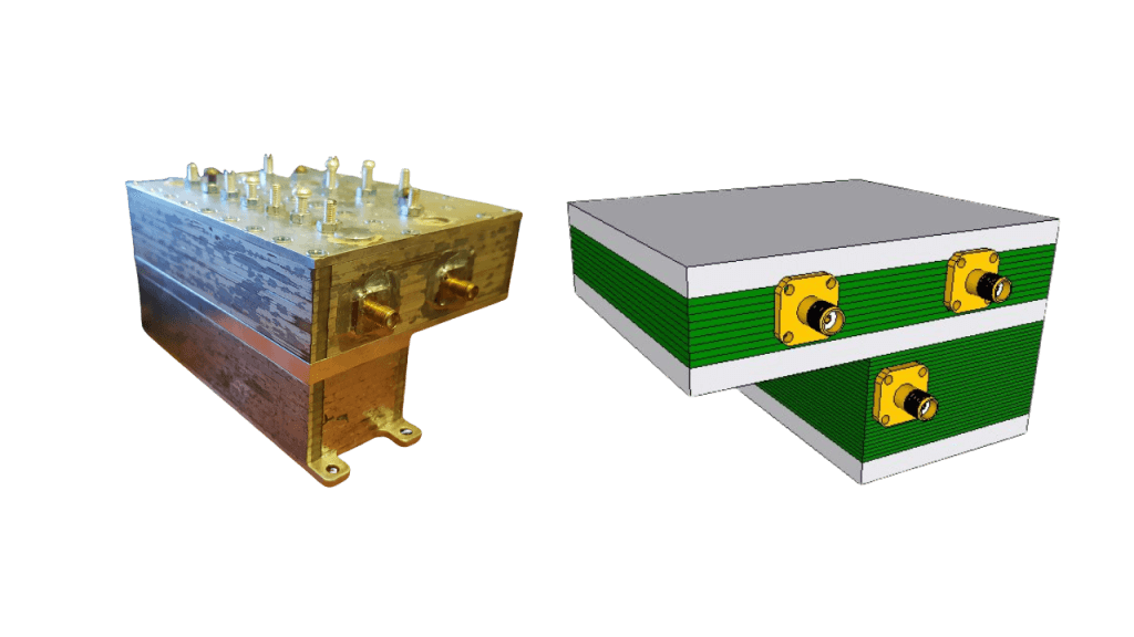
The connectors (in case the cavity is not a part of larger board) could be assembled by soldering from the outside, as shown on the prototype or be a part of the PCB design and assembled during PCBs integration

performancesfor a wide range of RF applications, including:
Cell towers Drones Satellites Other aerospace applications
Cost reduction
-The PCB raw material is much cheaper then aluminum cost The PCBs mass production is
-very cost effective. There is no need with additional silver plating process and opening
-formation stage since
it is inherent available with the PCB process.
Direct integration – Enable direct mounting and coupling of electric circuitries e.g., low noise amplifier, splitters, power amplifiers, switches, filter and any other on board PCB components directly on the PCB itself, which substantially improves system performance due to the direct connection (without connectors and cable loss), and significantly reduces system form factor

Integration Ability With Other Components Such As Combiner Switches, LNA Etc. Achieved On One Or More Layers
Using the PCB material within the resonator decrease the propagation length due to higher dielectric constant which decrease geometrical dimensions of the cavity resonators. This could be done with one or more layers
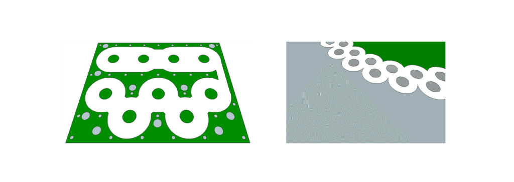
Internal Structure Which Enables Using Dielectric PCB Within The Cavity. The wight space in the left figure is a dielectric metrial and the vias are used as a wall of the dielectric propagation volume
Enables creating structures that are smaller than the regular ones for example a corrugated resonator, thereby reducing volume/size.
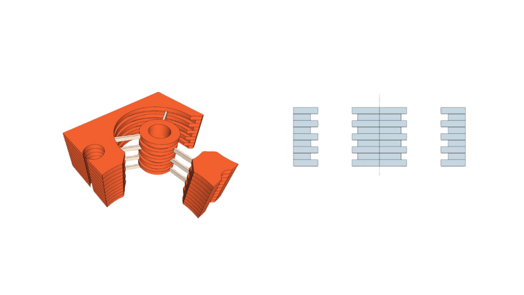
Internal Structure – Made For Size Reduction And/Or Extend Q
significant reduction in usage of materials and resources.
Manufacturing robustness: Usually the coupling mechanism to the resonator is hand prepared wired needed to be manually set into proper position. The PCB structure enable inherent manufacturing of this component enhancing the robustness of the manufacturing prosses
Different orientation design: The multilayered structure is used to form cavity structures having a myriad of orientations, allowing cavities extending in traversal and/or diagonal directions, which are not possible in the conventional manufacture techniques.